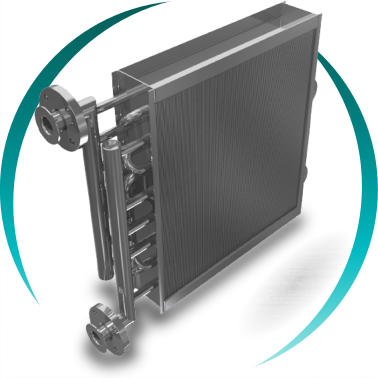
Continuous fins and tubes heat exchanger
A fins and tubes heat exchanger with continuous fins is an air–fluid heat exchanger designed to maximize thermal transfer efficiency when air or gas is the primary limiting factor of the process.
The BOIXAC continuous fins and tubes heat exchanger is specifically engineered for high-efficiency industrial processes where it is essential to maximize the heat transfer surface on the air or gas side while ensuring continuous operational reliability, mechanical and structural stability, and a compact, optimized design.
This type of heat exchanger operates with high thermal conductivity fluids such as water, water-glycol mixtures, steam, thermal oil, and diathermic fluids. It is particularly suitable for applications where air or gas limits overall performance, including industrial HVAC, cooling systems, air and gas treatment, and energy recovery systems.
The continuous fins integrally bonded to the tubes significantly increase the heat transfer surface area on the air side—typically the thermal bottleneck of the system—thereby increasing the overall heat transfer coefficient (U). This allows for reduced equipment size, weight, energy consumption, and total installation cost, without compromising performance or long-term reliability.
Industrial manufacturing and regulatory compliance
The mechanical tube-to-fin expansion manufacturing process ensures optimal, permanent, and uniform thermal contact, guaranteeing high thermal efficiency, structural stability, and consistent long-term performance, even under continuous operation in demanding industrial environments.
All BOIXAC fins and tubes heat exchangers comply with the European Pressure Equipment Directive 2014/68/EU (PED) and can be manufactured in accordance with ASME standards when required by the project, market, or client. This ensures operational safety, full documentation traceability, regulatory compliance, and international acceptance.
Advanced design of fins and tubes heat exchangers
At BOIXAC, we develop fully customized fins and tubes heat exchangers, designed using advanced thermal calculations, realistic industrial maintenance criteria, and material selections aligned with actual process conditions.
Each design aims to achieve the optimal balance between thermal performance, pressure drop, durability, ease of cleaning, and equipment lifespan, maximizing the client’s return on investment (ROI).
Key design decisions for fins and tubes heat exchangers
Tube selection
Tube diameter, wall thickness, and material are defined according to operating pressure, chemical compatibility, and corrosion risk.
Common materials: carbon steel, stainless steel AISI 304 / AISI 316, copper, copper-nickel, and titanium.
Fin material and fin pitch
Available materials: aluminum, Al5754, pre-coated aluminum, hydrophilic or hydrophobic aluminum, galvanized steel, stainless steel, copper, or titanium.
Fin pitch is optimized based on expected fouling, condensation, freezing risk, and cleaning strategy.
Tube bundle geometry
Staggered arrangement: higher turbulence and superior heat transfer coefficient (U).
In-line or square arrangement: lower pressure drop, improved accessibility, and easier maintenance.
Headers and fluid boxes
Sized according to fluid type, flow rate, operating pressure, and thermal cycling conditions.
Protective coatings and surface treatments
Internationally recognized industrial coatings such as Blygold, Heresite, Electrofin, or Aqua Aero, particularly suitable for aggressive or corrosive environments.
Tube bundle configuration and fin pattern
The tube layout and fin pattern directly affect thermal performance, pressure drop, cleanability, and equipment service life.
Staggered tube arrangement
Increases turbulence and heat transfer per unit surface area. Recommended for high thermal demand processes, accepting a higher pressure drop.

| P60 | Geometry 60 x 30 mm | Ø 16 mm tubes | HVAC and refrigeration | |
|---|---|
| Tube material | Cu, CuNi, Fe, AISI304, AISI316, titanium |
| Fin material | Al, AlMg2.5m, AlEpoxy, AlHy, Cu, AISI304, AISI316 |
| Remarks | Fin pitch from 1.6 to 6.0 mm and fin thickness from 0.11 to 0.23 mm |

| P40 | Geometry 40 x 35 mm | Ø 16 mm tubes | Refrigeration, air conditioning and energy recovery | ||
|---|---|---|
| Tube material | Cu, CuNi, Fe, AISI 304, AISI 316, Titanium | |
| Fin material | Al, AlMg2.5m, AlEpoxy, AlHy, Cu, AISI 304, AISI 316 | |
| Remarks | Fin spacing from 1.6 to 6.0 mm. Thickness 0.11 to 0.23 mm | |

| P25 | Geometry 25 x 19.05 mm | Ø 9.5 mm tubes | Multifunctional, R410A and CO2 | |
|---|---|
| Tube material | Cu, CuNi |
| Fin material | Al, AlMg2.5m, AlEpoxy, Cu, AISI304, AISI316 |
| Remarks | Fin spacing from 1.6 to 6.0 mm and thickness from 0.11 to 0.23 mm |
Inline / grid / square tube arrangement
Reduces pressure drop and facilitates cleaning. Recommended for environments with moderate dust levels or high maintenance requirements.

| P30 | 30 x 30 mm geometry | Ø 16 mm tubes | Commercial refrigeration and low temperature | |
|---|---|
| Tube material | Cu, CuNi |
| Fin material | Al, AlMg2.5m, AlEpoxy, AlHy, Cu, AISI304, AISI316 |
| Remarks | Fin pitch from 1.6 to 8.0 mm and fin thickness from 0.11 to 0.23 mm |
If you need to compare continuous fins with helical fins before deciding which technology best suits your process, consult the cluster page for finned tube heat exchangers:
Typical ROI
3-12 months
Efficiency
up to 90%
Warranty
2 years
Welding
up to 70% less
FAQs
What is a fins and tubes heat exchanger?
A fins and tubes heat exchanger is an air–fluid heat exchanger that uses continuous fins to maximize thermal transfer when air is the limiting factor.
In industrial applications, it increases the overall heat transfer coefficient, reduces equipment size, and improves energy efficiency in air- or gas-based processes.
What is the difference between continuous fins and helical fins?
Continuous fins maximize heat transfer surface area, while helical fins maximize mechanical robustness.
Continuous fins are optimal for clean, compact environments. Helical fins perform better in dusty conditions or where frequent cleaning is required, preventing performance degradation.
Which applications are best suited for continuous fins?
Industrial HVAC, cooling systems, air treatment, and energy recovery applications.
Especially suitable when air or gas limits heat exchange performance and available space is critical.
When are continuous fins recommended – and when are they not?
They are recommended when air limits heat transfer and maximum efficiency per unit volume is required.
They are not recommended in cases of severe fouling, abrasive particles, or aggressive cleaning, where helical fins, bare tubes, or pillow plate technology are preferable.
What data is required to select a finned coil?
At least 5 key parameters and the maximum available dimensions must be provided.
Depending on whether it is an HVAC coil, a refrigeration coil, a condenser coil, or an evaporator coil, data such as fluid types, flow rates, gas inlet temperature and humidity, liquid inlet temperature, and condensation or evaporation temperature may be required. Where applicable, specify the desired objective and any material or dimensional constraints.
What is a diathermic fluid?
A diathermic fluid is a thermal fluid that allows heat transfer at high temperatures without high operating pressures.
It is used in closed industrial circuits, reactors, furnaces, and continuous processes, providing thermal stability and operational safety. Examples include mineral thermal oils, synthetic oils, silicone fluids, and specialized high-temperature fluids.
Why choose BOIXAC for your fins and tubes heat exchangers?
Because we design each heat exchanger specifically for your process.
We combine advanced thermal calculations, high-quality materials, and proven experience in critical industrial sectors, ensuring efficiency, reliability, and measurable results.
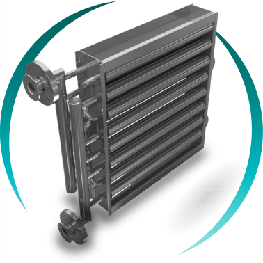
Finned tubes heat exchanger
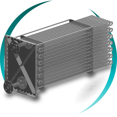
Smooth tubes heat exchanger
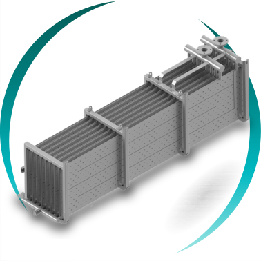
Dimple plate heat exchanger