Industrial finned tubes heat exchanger: Continuous and helical fins
An industrial finned tube heat exchanger is equipment that transfers thermal energy between two fluids —typically a gas and a liquid— through a bundle of metal tubes fitted with fins to extend the heat transfer surface. The central design decision is not the type of fluid, but which side limits the overall transfer: when the gas is the limiting fluid, the fins increase the effective surface on that side and make heat exchange viable under conditions where bare tubes would not be sufficient. The choice between continuous fins and helical fins depends on the fouling level, mechanical requirements and the installation environment.
Finned tube heat exchangers with process engineering
At BOIXAC we design custom finned tube heat exchangers, always starting from the analysis of the limiting fluid and the actual process. We do not select the technology before understanding the process: we first identify which side limits the transfer, what fouling level is acceptable and what mechanical requirements the installation imposes, and then define whether the optimal solution is a continuous fin bundle, a helical fin bundle, or a combination of both.
This design philosophy avoids oversizing, unnecessary pressure drops and equipment that degrades prematurely due to an incorrect fin type selection.
This page is the central hub of the BOIXAC finned tube heat exchanger cluster, providing an overview of the design decision and linking to the specific solutions: continuous fin tube heat exchanger and helical finned tube heat exchanger, where the construction details, available geometries and applications of each technology are developed.
The fundamental decision: identifying the limiting fluid
The choice between continuous fins and helical fins does not depend on whether the fluid is gas or liquid, but on which of the two sides limits the overall heat transfer of the exchanger.
The overall heat transfer coefficient U depends on the resistance of both sides. When both fluids have similar coefficients, the dominant resistance is the wall or fouling, and adding fins does not significantly improve performance. When there is a clear asymmetry —typically in gas-liquid processes, where the gas has a coefficient ten times lower than the liquid— the gas acts as the limiting fluid: in that scenario, the fins multiply the effective surface on the gas side and make heat exchange viable without excessively increasing equipment volume.
This limiting fluid analysis is the starting point of every heat exchanger project at BOIXAC. Only once it has been identified does it make sense to decide which type of solution is most appropriate.
Do you have a process where you need to integrate heat exchange into existing equipment?
Typical technical parameters of industrial tube heat exchangers
The following table shows the usual technical ranges of BOIXAC industrial tube heat exchangers, both with continuous fins and helical fins. The exact values depend on the fluid, bundle geometry, and process requirements.
| Parameter | Typical range | Conditioning factors |
|---|---|---|
| Typical internal fluid | Water, steam, thermal oil | High transfer coefficient |
| Typical external fluid | Air, process gas, flue gas | Limiting fluid → fins required |
| Internal fluid temperature | Up to 350°C (continuous fin) | Conditioned by fin material |
| Internal fluid temperature | Up to 600°C (helical fin) | Greater mechanical robustness of fin |
| Working pressure | Up to 40 bar | PED Directive 2014/68/EU where applicable |
| Typical thermal efficiency | Up to 90% | Fin geometry, pitch, air flow rate |
| Typical tube material | Cu, CuNi, AISI 304/316, Ti | Compatibility with internal fluid |
| Continuous fin material | Al, AlEpoxy, Cu, AISI 304 | External environment, temperature, corrosion |
| Helical fin material | Al, AISI 304, AISI 316 | Robustness, fouling, temperature |
Indicative values. Exact sizing requires limiting fluid identification and specific thermal calculation. Contact our technical team for your application.
Direct benefits of finned tube heat exchangers
Integrating a finned tube heat exchanger produces direct and quantifiable benefits in the process:
- Overcoming the limitation imposed by gas as a low-coefficient fluid, enabling exchange in gas-liquid processes
- Reduction in equipment volume and weight compared to bare tube solutions for the same thermal output
- Precise adaptation to the process fouling level through correct fin geometry selection
- Compliance with PED Directive 2014/68/EU and optionally ASME, with full documentary traceability
- Compatibility with demanding fluids: live steam, thermal oil, superheated water and diathermic fluids
- Reduction in operating costs through ROI-oriented design (typical ROI 3–12 months)
Industrial applications of finned tube heat exchangers
Waste heat recovery from industrial flue gases
Heat recovery from flue gases in furnaces, turbines or cogeneration engines is the most demanding application for finned tube heat exchangers. The hot gas —limiting fluid— flows over the tubes while the internal fluid absorbs the recovered energy. Helical fins are the preferred solution here due to their tolerance of dust and particles in flue gases.
Industrial air conditioning and ventilation
In HVAC systems for industrial buildings, data centres and process buildings, the continuous fin tube heat exchanger is the standard solution: air flows over the finned bundle while the internal fluid —water, water-glycol mixture or refrigerant— performs the transfer. The continuous fin maximises surface area per unit volume in clean or moderately clean air environments.
Process cooling systems
In manufacturing processes where a process fluid must be cooled before the next stage —chemical reactors, hydraulic oil circuits, compressors— the forced-fan finned tube heat exchanger offers an autonomous and efficient solution without requiring cooling water.
Combustion air preheating
When combustion air must be preheated using residual heat from outlet flue gas, the finned tube heat exchanger acts as a heat recovery unit. In this context, finned tube heat exchangers are used when outlet flue gas requires more accessible cleaning than continuous fin equipment provides.
Food and pharmaceutical industry with process gases
In processes where a clean gas —nitrogen, sterile air, dilute steam— must be heated or cooled with water or steam, continuous fin heat exchangers with sanitary materials (AISI 316L, titanium) deliver the highest performance per volume with full regulatory traceability.
Industrial drying and air treatment
In drying systems for solid or pasty products, the process air —limiting fluid— must be preheated or cooled with hot water, steam or refrigerant. The continuous fin tube heat exchanger integrated into the air duct is the most common solution, allowing the equipment to be sized according to the actual flow, temperature and humidity conditions.
The finned heat exchanger I need for my process
The choice between continuous fins and helical fins does not depend on preference, but on the analysis of fouling, mechanical requirements, and external gas conditions. The following table provides guidance for the initial selection:
| Technology | Fin type | Fouling | Mechanical robustness | Space | Typical application |
|---|---|---|---|---|---|
| Continuous fin tubes | Continuous (bonded to tube) | Low–moderate | Standard | Very compact | HVAC, refrigeration, clean gases |
| Helical finned tubes | Helical (independent) | Moderate–high | High | Compact | Flue gases, steam, thermal oil |
Final selection requires limiting fluid analysis and process fouling assessment. BOIXAC defines the optimal technology based on detailed analysis of each application.
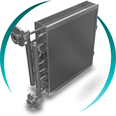
Perforated metal sheets perpendicular to the tubes. Maximum thermal efficiency per volume in clean external gas environments with critical space constraints.
View solutions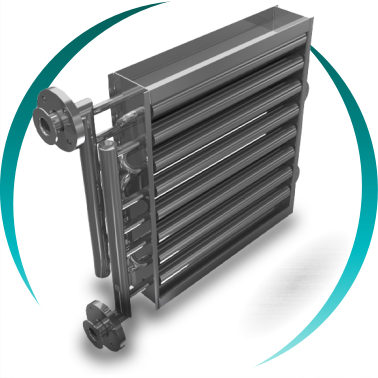
Helical fin individually pressed onto each tube. High robustness for industrial process with high-temperature gases, fouling or intense thermal cycles.
View solutionsCritical design factors for finned tube heat exchangers
- Identification of the limiting fluid: analysis of transfer coefficients on both sides
- External gas fouling level: determines fin geometry and pitch
- Maximum internal fluid temperature: determines tube and fin material
- Working pressure and applicable standard: PED 2014/68/EU, ASME
- Allowable pressure drop on the gas side: affects fin pitch and bundle arrangement
- Surface protection treatments according to environmental aggressiveness
External gas fouling: the factor that most influences fin selection
The continuous fin maximises thermal efficiency per unit volume, but its densely packed geometry makes it sensitive to fouling. In environments where the external gas contains dust, particles, oil or moderate dirt, the continuous fin can gradually clog, degrading performance to levels requiring costly cleaning or early equipment replacement.
The independent helical fin, with greater spacing between fins and greater thickness, tolerates moderate fouling better and allows mechanical cleaning without surface damage. In demanding industrial environments —flue gases with particles, combustion fumes with soot, environments with industrial dust— the helical fin is the solution with the lowest long-term maintenance cost.
At BOIXAC we define the fin type and pitch based on the expected fouling analysis for the specific process, not generic criteria. Incorrectly sized fin pitch is the main cause of premature performance loss in finned tube heat exchangers.
Frequently asked questions about industrial finned tube heat exchangers
When are fins necessary in a tube heat exchanger?
When a fluid (usually gas) has low transfer; fins increase surface area and improve performance.
When one of the two fluids has a heat transfer coefficient significantly lower than the other, limiting the overall exchanger performance. This typically occurs in gas-liquid processes, where the gas has a coefficient 4 to 20 times lower than the liquid. In that case, fins increase the effective surface on the gas side, compensating for its low conductance and enabling exchange in a reasonably sized unit.
What is the difference between continuous fins and helical fins?
Continuous: maximum efficiency in clean environments; helical: more robust, tolerate fouling and demanding conditions.
Continuous fins are perforated sheets joined to the complete tube bundle, creating a compact block of high surface density: maximum efficiency per volume, ideal for clean environments. Helical fins are wound individually around each tube, creating a robust surface with greater fin spacing: better fouling tolerance, greater thickness and lower risk of mechanical damage.
Can finned tube heat exchangers work with steam inside?
Yes, it is common; internal steam and external gas, helical fin preferred for robustness.
Yes, and it is one of their most common applications. Saturated, wet, superheated and flash steam can flow through the tubes while air or process gas flows over the external fins. Helical fins are preferred over continuous fins due to their greater robustness against thermal shocks and pressure variations typical of steam systems.
What materials are used for fins in corrosive environments?
Treated aluminium, AlMg, galvanised/stainless steel or titanium; special coatings in highly corrosive environments.
In environments with humidity, salinity or acid gases, standard aluminium may corrode prematurely. Common options for aggressive environments are: epoxy or hydrophobic-treated aluminium, AlMg2.5 aluminium for greater resistance, galvanised steel, AISI 304 or 316 stainless steel and, in extreme cases, titanium. For coastal installations or with halogen presence, industrial reference coatings such as Blygold, Heresite or Electrofin significantly extend finned bundle service life.
What regulations apply to finned tube heat exchangers in Europe?
PED in Europe; optional ASME for international projects as required.
Industrial finned tube heat exchangers operating above the pressure and volume thresholds defined in Directive 2014/68/EU (PED) must be categorised and verified in accordance with the corresponding conformity assessment procedures. BOIXAC designs and supplies PED-certified heat exchangers in the applicable categories depending on the fluid, pressure and nominal diameter.
How is a finned tube heat exchanger cleaned?
Depending on fin type: water, air or detergent; helical fins allow more aggressive cleaning; avoid high pressure on aluminium.
Cleaning strategy depends on the fin type and fouling level. Continuous fin bundles are typically cleaned with low-pressure water, detergent foam or air blowing. Helical fin bundles can withstand more aggressive mechanical cleaning due to their greater robustness and fin spacing. High-pressure water must never be used on aluminium fins, as the impact irreversibly deforms the sheets.
What is the typical ROI of an industrial finned tube heat exchanger?
Between 3 and 12 months; depends on energy cost, operation and process conditions.
The payback period typically ranges from 3 to 12 months for heat recovery applications in continuous industrial processes, depending on energy cost, annual operating hours and available temperature differential.
Can finned tube heat exchangers be designed for natural refrigerants such as CO₂ or NH₃?
Yes, compatible with CO₂ and NH₃ with appropriate design, materials and pressures.
Yes. Finned tube heat exchangers are compatible with natural refrigerants such as CO₂ (R744) and ammonia (R717), provided material selection, design pressure and manufacturing procedures are appropriate. CO₂ requires significantly higher design pressures (up to 130 bar in transcritical cycles). Ammonia is incompatible with copper and its alloys, so tubes and headers must be steel.
What is the difference between a finned tube heat exchanger and a shell and tube heat exchanger?
Finned: free external gas; shell-and-tube: confined fluids and high pressure, different applications.
These are technologies with radically different applications that do not compete with each other. The shell and tube heat exchanger is optimised for liquid-liquid or high-pressure gas-liquid exchange, with the external fluid contained within a closed shell. The finned tube heat exchanger is designed for processes where gas or air flows freely over the tube bundle in an open duct or partial casing.
Finned tube heat exchanger projects by BOIXAC
BOIXAC has designed and supplied finned tube heat exchangers in high-demand European industrial environments, including:
- Continuous fin tube coils for HVAC and heat recovery systems in industrial data centres, with R410A and high-pressure CO₂ refrigerants.
- Helical finned tube heat exchangers for thermal oil cooling in chemical process plants with fluid temperatures above 280°C.
- Finned bundles for combustion air preheating in biogas installations, with AISI 316L fins for tolerance to humidity and sulphurous compounds in biogas.
- Finned tube heat exchangers for industrial drying systems in the paper industry, with specific fin pitch sizing for fibre dust.
All these projects were developed starting from limiting fluid identification, expected fouling analysis and specific thermal and aerodynamic calculation.
Do you have a process with gas as the limiting fluid
Our technical team identifies the limiting fluid in your process, analyses the external gas fouling level and proposes the most suitable tube heat exchanger: continuous fins for maximum efficiency in clean environments, or helical fins for greater robustness in demanding applications.
We work with plant engineers, process managers and OEM equipment builders across Europe.