Heat Recovery Steam Generator (HRSG): the role of economisers and heat exchangers
Heat Recovery Steam Generator (HRSG) systems depend on the quality of their heat transfer components. This guide analyses the role of economisers and heat exchangers in optimising these systems, the determining design parameters and the selection criteria for demanding industrial applications.
In an industrial context where energy efficiency is a determining factor for competitiveness and regulatory compliance, recovering residual heat from exhaust gases represents one of the best cost-benefit interventions available. HRSG (Heat Recovery Steam Generator) systems are the reference solution for this application, and their overall efficiency depends largely on the quality and design of their heat transfer components: in particular, economisers and auxiliary heat exchangers.
1. HRSG system fundamentals
1.1 Definition and application context
An HRSG is a thermal recovery system that harnesses the enthalpy of hot exhaust gases from a gas turbine, internal combustion engine or industrial furnace to generate pressurised steam. This steam can be used for electricity generation in combined cycles, industrial heat processes or centralised district heating systems.
The main applications of HRSGs include combined cycle gas-steam power plants (CCGT), industrial cogeneration facilities, petrochemical plants and refineries, and processes in the paper, cement and steel industries.
1.2 Thermal architecture and main components
A conventional HRSG operates with exhaust gases flowing in counter-current or cross-flow against the water-steam circuit. Energy is transferred successively through several thermal sections, each optimised for a specific temperature range:
400–650 °C at gas turbine outlet. Up to 900 °C in industrial furnaces.
Raises saturated steam temperature above the saturation point, preventing condensation in turbines.
Converts liquid water into saturated steam at constant pressure. Phase change zone.
Preheats feedwater to near saturation point, extracting residual energy from already-cooled gases.
90–180 °C under optimal conditions. The economiser is key to minimising this value.
In applications with sulphur-containing fuels, the gas temperature at HRSG outlet cannot be reduced below the acid dew point temperature (typically 120–150 °C for gases containing SO₂), to prevent sulphurous acid condensation on economiser surfaces. This parameter is a critical design limit that directly constrains the maximum achievable energy recovery.
2. The economiser in an HRSG system
2.1 Function and thermal positioning
The economiser is a gas-liquid heat exchanger positioned in the low-temperature zone of the HRSG, where exhaust gases have already transferred most of their energy to the evaporator and superheater. Its function is to extract residual enthalpy from these gases to preheat the boiler feedwater.
The energy gain is directly proportional to the temperature difference between the water entering and leaving the economiser. A well-designed economiser can raise feedwater temperature from the typical 40–80 °C at deaerator outlet to 180–240 °C, drastically reducing the energy the evaporator must supply to achieve phase change.
2.2 Key design parameters
Designing an economiser for an HRSG requires the simultaneous analysis of multiple thermal, mechanical and process parameters. The main determining factors are:
| Parameter | Typical range | Design impact |
|---|---|---|
| Gas inlet temperature | 200–650 °C | Determines material selection and potential corrosion regime |
| Gas outlet temperature | 90–200 °C | Limited by acid dew point; constrains maximum recovery |
| Water pressure | 10–180 bar | Defines tube wall thickness and PED requirements |
| Water inlet temperature | 40–120 °C | Risk of condensation in humid gases; may require recirculation |
| Pinch point temperature | 8–20 °C | Difference between saturation temperature and gas temperature at same section |
| Gas mass flow rate | Process-specific | Determines pressure drop on gas side and ID fan power |
| Particle content | 0–50 g/Nm³ | Determines free passage between fins and cleaning method required |
3. Heat exchangers: types and integration
Beyond the economiser itself, an HRSG system may incorporate various types of heat exchangers depending on the thermal needs of the associated process.
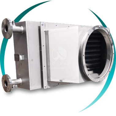
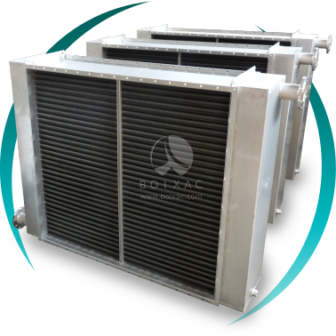
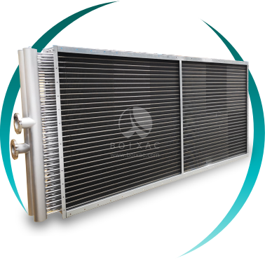
Preferred type for economisers in combustion gas streams with particulate content. Individual helical fins per tube provide greater mechanical robustness and vibration resistance. Fin pitch can be configured to minimise fouling in loaded gas streams.
Compact alternative for clean or filtered gases. Higher surface density per unit volume than helical fins, but requires particle-free gases to prevent inter-fin blockage. Common in combined-cycle gas turbine applications.
For applications where the internal fluid is high-pressure steam or water and the external fluid is a gas with high particle loading or corrosive compounds. The absence of fins simplifies external cleaning and reduces blockage risk.
In HRSG configurations coupled to burners, preheating combustion air with residual energy from exhaust gases improves burner efficiency and reduces fuel consumption. The gas-gas heat exchanger is the central component of this recovery.
4. Quantifiable benefits of thermal integration
Incorporating correctly sized economisers and heat exchangers in an HRSG system produces measurable improvements in several operational and environmental indicators.
A well-sized economiser can reduce gas outlet temperature by 80–150 °C, equivalent to recovering 3–8% of the total fuel energy burned. In combined-cycle plants, the economiser directly contributes to the overall electrical efficiency of the cycle.
Increasing feedwater temperature reduces the energy the evaporator must supply. For every 6 °C increase in feedwater temperature, boiler fuel consumption is reduced by approximately 1% under typical operating conditions.
Reduced need for additional fuel burning translates directly into lower CO₂ and NOₓ emissions per unit of energy produced. In sectors subject to emissions trading (EU ETS), this reduction has a direct, quantifiable economic value.
Preheating feedwater reduces the thermal gradient at the evaporator inlet, minimising thermal stresses on steam generator surfaces and extending component service life. Particularly relevant in operations with frequent start-ups and shutdowns.
A specific risk in economiser design for HRSGs is the phenomenon of local boiling (steaming): if water temperature at economiser outlet exceeds the saturation point at working pressure, partial vaporisation may occur inside the tubes, generating vibrations, water hammer and potential erosion. Conventional design establishes a safety margin of 5–15 °C below saturation temperature at outlet. Where process conditions are variable, recirculation or economiser bypass systems are provided.
5. Component selection criteria for HRSG
Selecting economisers and heat exchangers for integration into HRSG systems requires a detailed technical study going beyond nominal operating conditions.
- Process gas composition: presence of SO₂, HCl, suspended particulates, sulphur or nitrogen compounds that may generate acid corrosion or deposits on heat transfer surfaces.
- Load variation range: HRSGs coupled to variable-output turbines require heat exchangers designed to operate efficiently between 40% and 100% of nominal load, without risk of local boiling or condensation corrosion.
- PED regulatory requirements: economisers forming part of a boiler pressure circuit are subject to Directive 2014/68/EU (PED) and applicable industrial safety technical regulations.
- Materials and corrosion resistance: for sulphur-bearing gases, surfaces in contact with lower-temperature gases are typically specified in austenitic stainless steel or with acid corrosion-resistant coatings.
- Maintenance and cleaning access: in particulate-laden gases, the design must provide access for soot blower cleaning or dry cleaning without dismantling the heat exchanger.
- Integration into the overall HRSG: the hydraulic and aerodynamic connection of the economiser with the rest of the system must minimise additional pressure drops on both the gas and water sides.
BOIXAC Tech SL designs and supplies economisers and heat exchangers for integration into energy recovery systems, including HRSG applications. Each solution is developed from the client's actual process conditions: gas composition and temperature, working pressure, dimensional constraints and regulatory requirements. Our technical team works with project engineers to define the optimal solution for each plant configuration.